Popular Models of Common Capacitor Symbols
I. Introduction
Capacitors are fundamental components in electronic circuits, playing a crucial role in various applications, from energy storage to signal filtering. A capacitor is a passive electronic component that stores electrical energy in an electric field, allowing it to release that energy when needed. Their importance cannot be overstated, as they are integral to the functioning of countless devices, including smartphones, computers, and power supplies. This article aims to explore common capacitor symbols used in circuit diagrams, providing insights into their meanings and applications.
II. Understanding Capacitor Basics
A. What is a Capacitor?
A capacitor consists of two conductive plates separated by an insulating material known as a dielectric. When voltage is applied across the plates, an electric field forms, allowing the capacitor to store energy. The primary function of a capacitor is to store and release electrical energy, making it essential for smoothing out voltage fluctuations, filtering signals, and coupling or decoupling signals in circuits.
1. Function and Operation
Capacitors charge and discharge based on the voltage applied to them. When connected to a power source, they accumulate charge until they reach their voltage rating. When disconnected, they can release this stored energy to power other components in the circuit.
2. Types of Capacitors
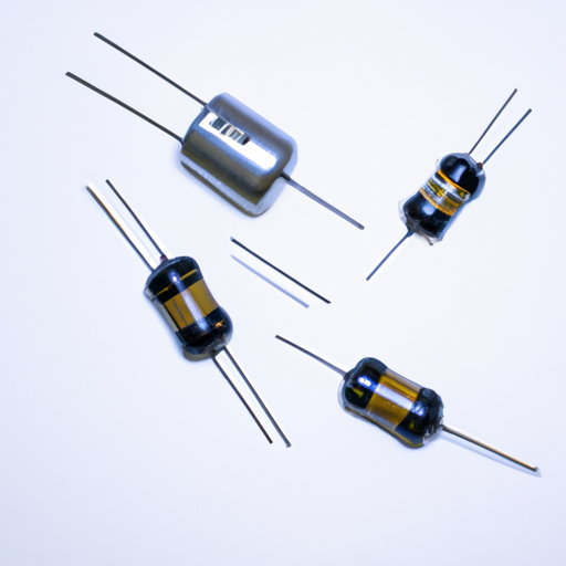
There are several types of capacitors, each with unique characteristics and applications:
Electrolytic Capacitors: Known for their high capacitance values, these capacitors are polarized, meaning they have a positive and negative terminal. They are commonly used in power supply circuits.
Ceramic Capacitors: These non-polarized capacitors are made from ceramic materials and are widely used in high-frequency applications due to their stability and low cost.
Film Capacitors: Made from thin plastic films, these capacitors are known for their reliability and are often used in audio applications and timing circuits.
B. Key Parameters of Capacitors
Understanding the key parameters of capacitors is essential for selecting the right component for a specific application:
1. Capacitance
Measured in farads (F), capacitance indicates the amount of charge a capacitor can store. Common subunits include microfarads (µF) and picofarads (pF).
2. Voltage Rating
The voltage rating specifies the maximum voltage a capacitor can handle without breaking down. Exceeding this rating can lead to failure or explosion.
3. Tolerance
Tolerance indicates the permissible variation in capacitance from its stated value. It is usually expressed as a percentage.
4. Equivalent Series Resistance (ESR)
ESR is a measure of the internal resistance of a capacitor, affecting its efficiency and performance, especially in high-frequency applications.
III. Common Capacitor Symbols in Circuit Diagrams
Understanding the symbols used to represent capacitors in circuit diagrams is crucial for engineers and technicians. Here are some of the most common capacitor symbols:
A. Standard Capacitor Symbol
The standard capacitor symbol consists of two parallel lines, representing the two conductive plates. This symbol is universally recognized and is used in most schematics to denote a capacitor.
B. Polarized Capacitor Symbol
Polarized capacitors, such as electrolytic capacitors, are represented by the standard symbol with a curved line indicating the positive terminal. This distinction is vital, as connecting a polarized capacitor in reverse can damage the component and the circuit.
C. Non-Polarized Capacitor Symbol
Non-polarized capacitors, like ceramic and film capacitors, are represented by the standard symbol without any additional markings. These capacitors can be connected in either direction, making them versatile for AC applications.
D. Variable Capacitor Symbol
Variable capacitors, which allow for adjustable capacitance, are represented by the standard symbol with an additional line or arrow indicating the adjustable feature. These capacitors are commonly used in tuning circuits, such as radios.
E. Tantalum Capacitor Symbol
Tantalum capacitors, known for their stability and reliability, are represented by a symbol similar to the polarized capacitor but often include a specific marking to indicate their unique properties. These capacitors are frequently used in compact electronic devices.
IV. Specialized Capacitor Symbols
In addition to the common symbols, there are specialized symbols that indicate specific characteristics of capacitors:
A. Capacitor with a Specific Voltage Rating
Some schematics include voltage ratings next to the capacitor symbol, indicating the maximum voltage the capacitor can handle. This information is crucial for ensuring the capacitor is suitable for the circuit's requirements.
B. Capacitor with a Specific Capacitance Value
Capacitance values are often represented next to the capacitor symbol, allowing engineers to quickly identify the required capacitance for their designs. This practice aids in component selection and ensures the circuit functions as intended.
C. Capacitor with a Specific Tolerance
Tolerance can also be indicated next to the capacitor symbol, providing insight into the expected variation in capacitance. This information is essential for applications where precision is critical.
V. Understanding Capacitor Symbol Variations
A. Regional Differences in Capacitor Symbols
Capacitor symbols can vary by region, with different conventions used in North America compared to Europe. Understanding these differences is essential for engineers working in international contexts, as misinterpretation can lead to design errors.
B. Industry-Specific Symbols
Certain industries may adopt unique symbols for capacitors based on their specific needs. For example, automotive electronics may use different symbols than consumer electronics. Recognizing these variations is crucial for accurate communication and design.
VI. Practical Applications of Capacitor Symbols
A. Reading and Interpreting Circuit Diagrams
For engineers and technicians, understanding capacitor symbols is vital for reading and interpreting circuit diagrams. Misunderstanding a symbol can lead to incorrect component selection or circuit design, resulting in malfunction or failure.
B. Designing Circuits with Capacitors
When designing circuits, selecting the right capacitor based on its symbol and specifications is crucial. Accurate representation in schematics ensures that the circuit will perform as intended, minimizing the risk of errors.
VII. Conclusion
In conclusion, capacitor symbols are an essential aspect of electronic circuit design and interpretation. Understanding these symbols and their meanings is crucial for engineers and technicians working in the field. As technology continues to evolve, the role of capacitors in modern electronics remains significant, making it imperative for professionals to stay informed about the latest developments and standards. We encourage further study and exploration of electronic components, as a deeper understanding of capacitors and their symbols can lead to more effective and innovative designs.
VIII. References
For those interested in further learning, the following resources are recommended:
- "The Art of Electronics" by Paul Horowitz and Winfield Hill
- "Electronic Components: A Complete Reference for Project Builders" by Mark J. Balch
- Relevant standards and guidelines from organizations such as the Institute of Electrical and Electronics Engineers (IEEE) and the International Electrotechnical Commission (IEC).
By familiarizing yourself with capacitor symbols and their applications, you can enhance your understanding of electronic circuits and improve your design skills.

